
Page 271 - floMAX Catalogue 2016
P. 271
STANDARD SERIES FRL - “NEW DEAL” 5
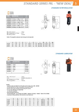
STANDARD FILTER REGULATOR
CODE DESCRIPTION €
P11
1225030 20 Micron 0-8bar G1/4” 48.10
1225054 20 Micron 0-12bar G1/4” 48.10
1325030 20 Micron 0-8bar G3/8” 71.16
1325054 20 Micron 0-12bar G3/8” 71.16
1425030 20 Micron 0-8bar G1/2” 71.16
1425054 20 Micron 0-12bar G1/2” 71.16
Max. inlet pressure 18 bar
Max temperature at 10 bar 50 °C
Mounting position Vertical
Notes: The regulator pressure must always be set upwards
A B C D E F G I L M N P kg
G 1/4” 42 190 42 42 36 30x1.5 10 121 M4 Hole 145 G1/8” 233 0.5
G 3/8” 60 245 60 60 52 30x1.5 14 150 M4 Hole 185 G1/8” 295 1.0
G 1/2” 60 245 60 60 52 30x1.5 14 150 M4 Hole 185 G1/8” 295 1.0
STANDARD LUBRICATOR
CODE DESCRIPTION €
1223001 G1/4” P11
1323001 G3/8”
1423001 G1/2” 42.17
1523001 G3/4” 49.74
1623001 G1” 49.74
134.42
134.43
Max. inlet pressure 18 bar
Fluid Filtered compressed air
Max temperature at 10 bar 50 °C
Mounting position Vertical
NOTES:
• Use the screw provided to set the drip rate to drop every 300 - 600 Ml.
• Fit the lubricator as close as possible to the point of use
• Fill the bowl with oil before pressurising the system
• Do not use cleaning oil, brake fluid
or solvents in general
• Recommended lubricants:
ISO and UNI FD22 - E.g. Energol HLP 22(BP) - Spinesso 22 (Esso) - Mobil) - Tellus Oil 22 (Shell)
• Automatic filling lubricator and minimum level lubricator
A B C D E G I L M kg
G 1/4” 42 156 42 42 32 10 121 M4 Hole 176 0.4
G 3/8” 60 195 60 60 46 14 136 M4 Hole 220 0.9
G 1/2” 80 195 80 80 66 22 182 M4 Hole 290 0.9
G 3/4” 80 260 80 80 66 22 182 M6 Hole 290 1.8
G 1” 80 260 80 80 66 22 182 M6 Hole 290 1.8
265