
Page 241 - floMAX Catalogue 2016
P. 241
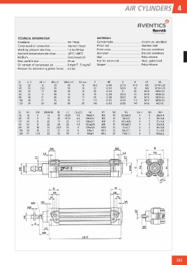
AIR CYLINDERS 4

TECHNICAL INFORMATION	                                            MATERIALS
Standards
Compressed air connection	               ISO 15552                Cylinder tube	               Aluminum, anodized
Working pressure min./max. 	             Internal thread
Ambient temperature min./max.	           1.5 bar/10 bar           Piston rod	                  Stainless steel
Medium	                                  -20°C / +80°C
Max. particle size	                      Compressed air           Front cover	                 Die-cast aluminum
Oil content of compressed air	           50 µm
Pressure for determining piston forces	  0 mg/m3 - 5 mg/m3        End cover	                   Die-cast aluminum
                                         6,3 bar
                                                                  Seal	Polyurethane

                                                                  Nut for piston rod	          Steel, galvanized

                                                                  Scraper	Polyurethane

Ø	 A -2	  AF +1	  ØB d11	                ØBA d11	  BG min.	        E	     EE	            G	    H	 KF	           KK
32	 22	     12	      30	                     30	      16	         46.5	  G 1/8	        27.75
40	 24	    13.5	     35	                     35	      16	          53	   G 1/4	        33.25	  47.5	M6	M10x1,25
50	 32	     17	      40	                     40	      16	          65	   G 1/4
63	 32	     17	      45	                     45	      16	          75	   G 3/8	         31	    53	M8	M12x1,25
80	 40	     21	      45	                     45	      17	          95	   G 3/8	        38.25
100	 40	    21	      55	                     55	      17	         115	   G 1/2	        38.25	  65	M10	M16x1,5
125	 54	    28	      60	                     60	      20	         140	   G 1/2	        42.25
                                                                                       53.85	  75	M10	M16x1,5

                                                                                               95	M12	M20x1,5

                                                                                               115	M12	M20x1,5

                                                                                               140	M16	M27x2

Ø	 KV	 KW	 ØMM f8	 PL	 L2	 L3±0,5	                           L8	         RT	 SW	       TG	     VA -1	 VD	       WH

32	16	 5	 12	 16	16.25	 4.5	 94±0,4	 M6	 10	32,5±0,5	 4	 5	26±1,4

40	 18	 6	 16	 20	18.25	 4.5	 105±0,7	M6	 13	38±0,5	 4	 5	30±1,4

50	24	8	 20	19	25	4.5	106±0,7	 M8	 17	46,5±0,6	 4	 5	37±1,4

63	24	8	 20	24	25	4.5	121±0,8	 M8	 17	56,5±0,7	 4	 5	37±1,8

80	30	 10	 25	 23.5	33	 0	 128±0,8	M10	 22	 72±0,7	 4	 5	46±1,8

100	30	 10	 25	 25	 36	 0	 138±1	 M10	22	89±0,7	 4	 5	51±1,8

125	41	13.5	 32	 33	45	 0	 160±1	 M12	 27	110±1,1	 6	 7	65±2,2

                                                                                                                     235