
Page 218 - floMAX Catalogue 2016
P. 218
3 MULTIMACH VALVE SYSTEM
HDM is the ideal solution for those requiring the unbeatable
performance, flexibility and modularity of Multimach valves combined
with sturdy mechanics and a high degree of protection against external
agents. Each valve is enclosed in a reinforced technopolymer protective
shell that acts as a shock-absorber and prevents the infiltration of dirt.
The class of protection is IP65. The smooth, rounded design makes
HDM ideal for applications requiring frequent washing without the
deposit of residues. All the pneumatic connections are on one side,
with built-in push-in fittings. The user interface is on another side so
the fitter and service engineer have everything at hand. Flexibility is
total: there are 1-16 valves, input and output terminals for pipes of
different sizes and intermediate modules for separate inputs and
outputs. One very important new feature is that valves of different
capacities can be mounted as required. Three different valve sizes can be combined at will. This means a valve can be
replaced at any time by another one offering a different performance. It only takes a few seconds to replace or add
a valve. To do this, merely loosen the two grub screws fixing the valve to the adjacent ones. Since the electrical signal
is relayed from one valve to the next by means of gold-plated contacts connected to an electronic
board, the electrical connections are entirely automatic.
The ratio of the HDM’s flow rate to its dimensions unrivalled - miniaturisation and efficiency have
reached a peak.
TECHNICAL DATA
Valve port connections quick-connection ports 2 and 4, Ø 4, 6, 8 mm threaded exhaust port 3/8 or fitting Ø8 mm
Connection on the end-plate for the supply of pilots Automatic fitting Ø 4
Maximum number of pilots 16
Maximum number of valves 16 (same as the max. no. of pilots)
Operating temperature range ˚C -10 ÷≤+60
Fluid rate 6 bar ∆P 1 bar NI/min 11mm Ø 4 = 200 11mm Ø 6 = 500 14mm Ø 8 = 800
Pressure range X (pilot supply) 1-11 (valve supply)
- terminal 1-11 2 ÷ 7 bar vacuum at 10 bar
- terminal 1 2 ÷ 7 bar
Voltage range 24 VDC ± 10%
Power W 0,6
Control PNP o NPN
Insulation class F155
Degree of protection IP65 with common outlets
Solenoid rating 100% ED
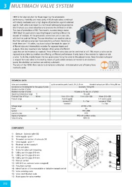
COMPONENTS
1) Exhaust - Solenoid pilot 8/2
2) Valve supply - port 1
3) Threaded connection of exhausts 3/5
4) Valve supply - port 11
5) Electrical control supply X
6) Blind end-plate
7) Screw for valve wall-mounting
8) Utility port for pipe Ø 8 mm
9) Utility port for pipe Ø 6 mm
10) Utility port for pipe Ø 4 mm
11) Manual control
12) LED (LED on, solenoid valve energised)
13) Pneumatic symbol
14) Identification of the monostable or bistable manual control
15) Valve ordering code
16) Valve identification code
17) Blank space for valve number
212