
Page 223 - floMAX Catalogue 2016
P. 223
SPECIAL PURPOSE VALVES 3
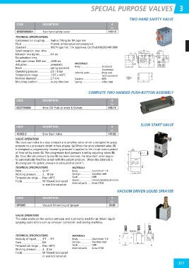
TWO HAND SAFETY VALVE
CODE DESCRIPTION €
P06
W3605000001 Two hand safety valve 159.13
TECHNICAL SPECIFICATIONS
Compressed air couplings Push-in fitting for Ø4 pipe mm
Fluid Filtered, unlubricated compressed air
Standard EN574 type IIIA, TUV approved, Certified M6020244919001
Synchronisation, max. time
between two signals 0.4 sec
De-activation time,
with pipe L=max 1000 mm <0.05 sec MATERIALS
Actuation pneumatic Body Anodised
Reset spring operated Aluminium
Operating pressure 2.5 ÷ 8 bar Internal parts Brass and
Temperature range -10˚C ÷ +60˚C technopolymer
Nominal diameter 2.7 mm Gaskets NBR
Mounting position in any direction Spring Alloy steel
COMPLETE TWO HANDED PUSH-BUTTON ASSEMBLY
CODE DESCRIPTION €
P06
0227700000 4mm OD Push-in Inlets & Outlets 458.13
CODE DESCRIPTION € SLOW START VALVE
N17
10.003.3 Slow Start Valve 145.85
VALVE OPERATION
The slow-start valve is a very compact and sensitive valve which is designed to apply
pressure to a pneumatic circuit in two phases. (a) When the pilot solenoid valve (X)
is energised a progressively increasing pressure is applied to the circuit over a period
of time set by screw (S). The progressive start pressure is set by adjusting screw (R)
(b). Once the set pressure (screw R) has been reached, the slow-start valve begins
to automatically feed the circuit with the system pressure. When the solenoid is
de-energised the system pressure is exhausted at point 1.
TECHNICAL SPECIFICATIONS MATERIALS
Ports G1/4” Body Aluminium 11S
Working pressure 2... 10 bar Springs Stainless steel
Temperature range Max +60ºC Seals NBR
Fluids 50 filtered, lubricated Spools Nickel plated aluminium
or non lubricated air Internal parts Brass OT58
VACUUM DRIVEN LIQUID SPRAYER
CODE DESCRIPTION €
N17
DP2005 Vacuum Driven Liquid Sprayer 20.85
VALVE OPERATION
This valve works on the venturi principal and is primarily used for air driven liquid
spraying applications such as conveyor lubrication and sawing machines.
TECHNICAL SPECIFICATIONS MATERIALS
Viscosity of liquid 3ºE .... 5ºE Body Aluminium 11S
Ports M5 Springs Stainless steel
Temperature range Max +60ºC Seals NBR
Working pressure 3... 8 bar Internal parts Brass OT58
Fluids 50 filtered, lubricated
or non lubricated air
217