
Page 221 - floMAX Catalogue 2016
P. 221
SPECIAL PURPOSE VALVES 3
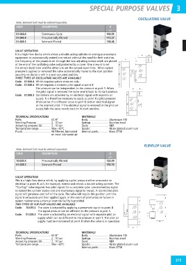
Note: Solenoid Coils must be ordered separately OSCILLATING VALVE
CODE DESCRIPTION €
N17
01.044.4 Continuous Cycle 106.03
113.27
01.046.4 Pneumatically Piloted 138.48
01.008.3 Solenoid Piloted
VALVE OPERATION
It is a high-flow device which allows a double acting cylinder or analogue pneumatic
equipment to automatically extend and retract without the need for limit switches.
the frequency of the phases is set through the two adjusting screws which are placed
at the end of the oscillating valve and protected by a cover. One screw is to set
the retract dwell time and the other is to set the extend dwell time. When system
pressure is applied or removed the valve automatically moves to the start position
ensuring no device is left in a semi-actuated position.
THREE TYPES OF OSCILLATING VALVES ARE AVAILABLE
Code: 01.044.4 Which requires system pressure only.
Code: 01.046.4 Which requires a constant pilot signal at point X.
The pressure can be independent to the pressure at port 1. When
the pilot signal is removed the valve reverts back to its start position.
Code: 01.008.3 Oscillations are activated by an electrical signal with separate air
supply. It is therefore necessary to apply to point X a pilot pressure
(that can be of a different value to port 1) and an electrical signal
at the solenoid pilot. If the electrical signal is removed or the pilot air
supply fails the valve reverts back to its start position.
TECHNICAL SPECIFICATIONS MATERIALS
Ports G1/4” Body: Aluminium 11S
Working Pressure 2...10 bar Springs: Stainless steel
Actuating pressure (X) 3...10 bar Seals: NBR
Temperature range Max +60°C Spools: Nickel plated aluminium
Fluids 50 filtered, lubricated Internal parts: Brass OT58
or noon lubricated air
Note: Solenoid Coils must be ordered separately FLIP/FLOP VALVE
CODE DESCRIPTION €
N17
10.035.4 Pneumatically Piloted
120.39
01.028.3 Solenoid Piloted 156.70
VALVE OPERATION
This is a high-flow device which, by applying a pilot pressure either pneumatic or
electrical to point X, will, for example, extend and retract a double acting cylinder. The
“flip-flop” valve requires two pilot signals for a complete cycle: one momentary signal
to extend the cylinder stroke and one momentary signal to retract. A maintained pilot
signal will generate one half of the cycle. The valve will stay in this position until the
signal is exhausted and then applied again. In the event of pilot pressure failure or
system maintenance a manual override facility is provided.
TWO TYPES OF FLIP-FLOP VALVES ARE AVAILABLE
Code: 10.035.4 The valve is actuated by applying a pneumatic signal to point X.
The signal pressure can be different to the pressure at port 1.
Code: 01.028.3 The valve is actuated by an electrical signal with separate pilot air
supply which can be different to the pressure at port 1. The pilot air
supply must be maintained at point X when the valve is in operation.
TECHNICAL SPECIFICATIONS MATERIALS
Ports G1/4” Body: Aluminium 11S
Working Pressure 2...10 bar Springs: Stainless steel
Actuating pressure (X) 3...10 bar Seals: NBR
Temperature range Max +60°C Spools: Nickel plated aluminium
Internal parts: Brass OT58
215